hi,
many people (inspector or engineer) doubt about DFT calibration. is it need to calibrated on flat surface or rough surface? want to know my opinion?
let’s share…
eventhough there are so many standard for DFT calibration, but in this article i only use two common standard, which are ISO 19840 and SSPC-PA2.
first, lets discuss about ISO 19840.
in ISO 19840 it is generally explained through paragraph 5.3 “material used for calibration are plastic shim, un-coated or pre-coated test plate” and paragraph 6.2 “adjustment of the instrument shall be carried out on un-coated test plate at zero with shims/foils below and above the specified DFT or in pre-coated test plates instead of verified shims/foils”.
the word un-coated test plate are describe as smooth, flat, clean free millscale, etc.
while the pre-coated test plate are describe as certified, smooth, flat, visually clean pre-coated steel test plates with assigned values traceable to recognised standards and with coating thicknesses near to the expected dry film thickness to be measured.
the calibration method are as follows:
- prepared un-coated flat test plate surface, i suggest you to use the un-coated test instead of pre-coated test plate due to pre-coated surface with values traceable to recognised standard is hard to obtain, and if available it is costly :).
- prepare shims/foils similar with specified DFT required. take 1 shims/foils which is near the specified DFT.
- select calibration method on your gauge. i suggest using zero method.
- place the shims on the un-coated flat test plate surface, and adjust the scale reading to the value of the shims/foils.
- finish and close the calibration, then back to the DFT reading panel. try to measure the shims/foils once again on the un-coated flat test plate surface.
- you have done your calibration on the un-coated flat test plate surface.
calibration on un-coated flat surface is required correction factor when it use to measure paint thickness on blasted/rough surface. flat surface calibration will give false paint thickness reading on blasted surface since the blasted surface characteristic having peak and valley point.
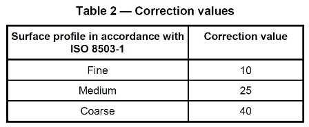
the DFT gauge will measure mean of the paint thickness on blasted surface area higher than actual because there are distance from valley of the blasted surface to the probe. while the actual paint thickness from peak of the blasted surface to the probe are less than specification. in this case, correction value added to reduce effect of the valley point from blasted surface. you will notice in paragraph 7 “correction value” as shown below:

this correction value is related to the blasted profile on your surface. example if you have surface profile on your blasted surface is 65 microns grit, then refer to ISO 8503-1 the grit comparator is between segment 2 to segment 3, so the range of the profile gauge is medium and the correction value to be used is medium or 25 microns.
once you know your correction value, subtracted the value from the individual reading every time you read the DFT of each layer. example, when you place your probe on the primer coat layer, you will see on your DFT gauge 80 microns DFT. this means you have to subtracted 25 microns from 80 microns. so the actual DFT of your primer coat is 80-25 = 55 microns. this correction value is applied on each layer you read the DFT. example on top coat layer is shown 200 microns. this means you have to subtracted 25 microns from 200 microns. so the actual DFT of your top coat is 200-25 = 175 microns. and so on..
optional..
sometimes the question then, if we use this correction value, why the reading film on DFT gauge is less than specification? the answer is YES, because the correction value is only take generally, as a mean.
however, ISO 19840 also mention in Appendix A that calibration also posible to do in rough surface or blasted area.
the calibration method are simple:
- prepare blasted surface same with actual painting production.
- prepare shims/foils similir with specified DFT required. take 2 shims/foils which are below (thinner shims) and above (thicker shims) specified DFT.
- select calibration method on your gauge, i suggest using rough surface/2 points method.
- place the thinner shims on the blasted surface, and adjust the scale reading to the value of the shims/foils.
- place the thicker shims on the blasted surface, and adjust the scale reading to the value of the shims/foils.
- finish and close the calibration, then back to the DFT reading panel. try to measure the shims/foils once again on the blasted surface.
- you have done your calibration on the blasted surface.
by using this Appendix A method, you dont need to use correction factor, no need to subtracted from the individual reading.
So, either using flat or rough surface is possible in accordance to ISO 19840.
optional, sometimes the question then, why the reading film on DFT gauge is less than specification? the answer is YES, because there are paint loss due to effect of ‘dead volume’.
so, if there are specification mention for primer DFT 75 microns (example volume solid 50%), the WFT should be minimum 150 microns, right? if you use this 150 microns WFT to achieve 75 microns DFT, your DFT reading on the DFT gauge ofcourse will be less. because the paint is absorb in the ‘dead volume’. so then to avoid less reading you have put additional thickness to cover the ‘dead volume’. YES, put additional 25 microns on your new DFT (or depends on you correction value, it may 10 25 or 40 microns). so if the specification mention for primer DFT 75 microns, you have put additional 25 microns DFT to cover the correction value. now the primer DFT should be 75 + 25 microns = 100 microns. and does the WFT will be 200 microns (example VS 50%). by this method you will have DFT reading same to the specification.
(to be continued.. for SSPC-PA2 method, i will update once available, just wait and see..)